

How to Find the Right Solution for Your Project
Fiber optic communications has been a rapidly expanding industry for the last 20 years. In its early years, it was mainly used for backhaul communications between large ISP’s. But now fiber is widely used and can be found almost anywhere. It’s probably in your office, on the telephone poles outside your home, and maybe even in your home. With the growth of the fiber industry, a wide array of fiber optic patch panels have been developed to fit the many needs of these varying environments.
If you already know what your project requires, check out our complete Fiber Patch Panel selection.
What is a Fiber Patch Panel?
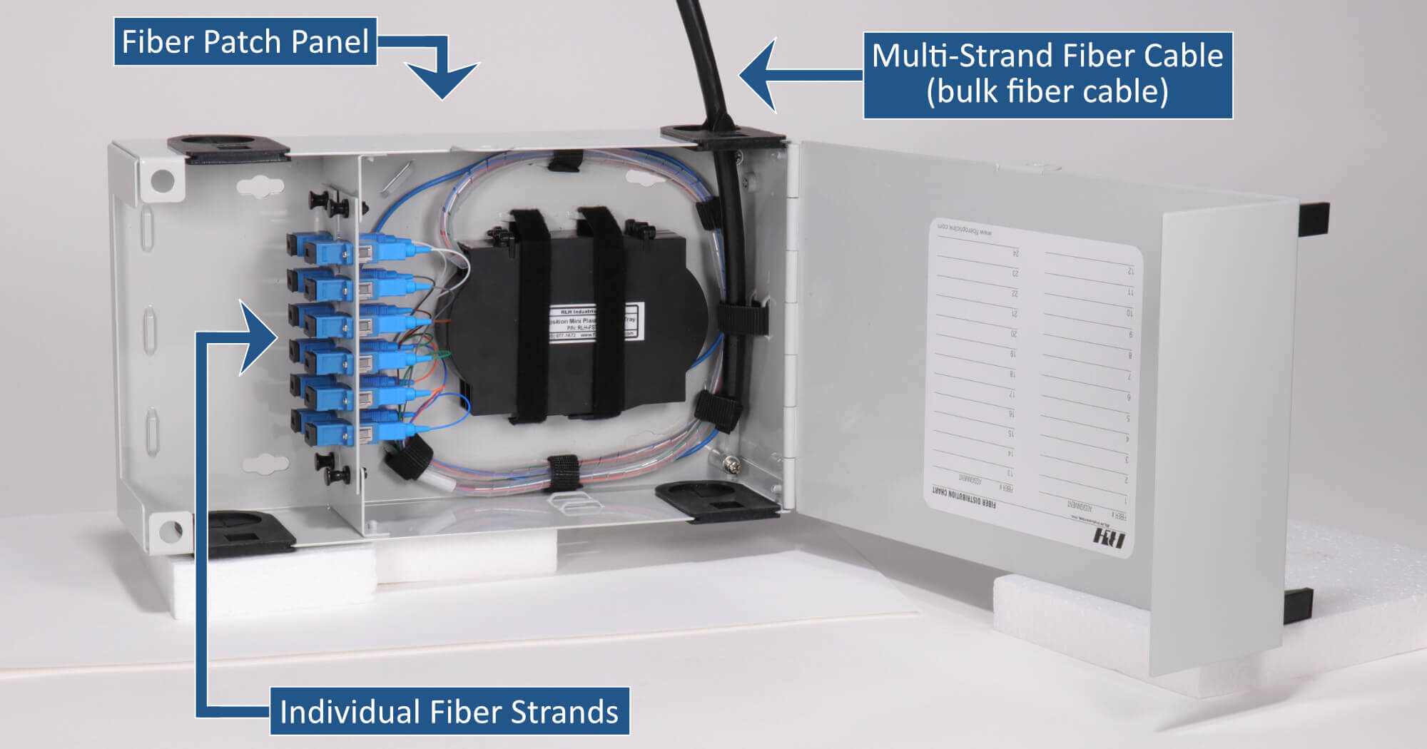
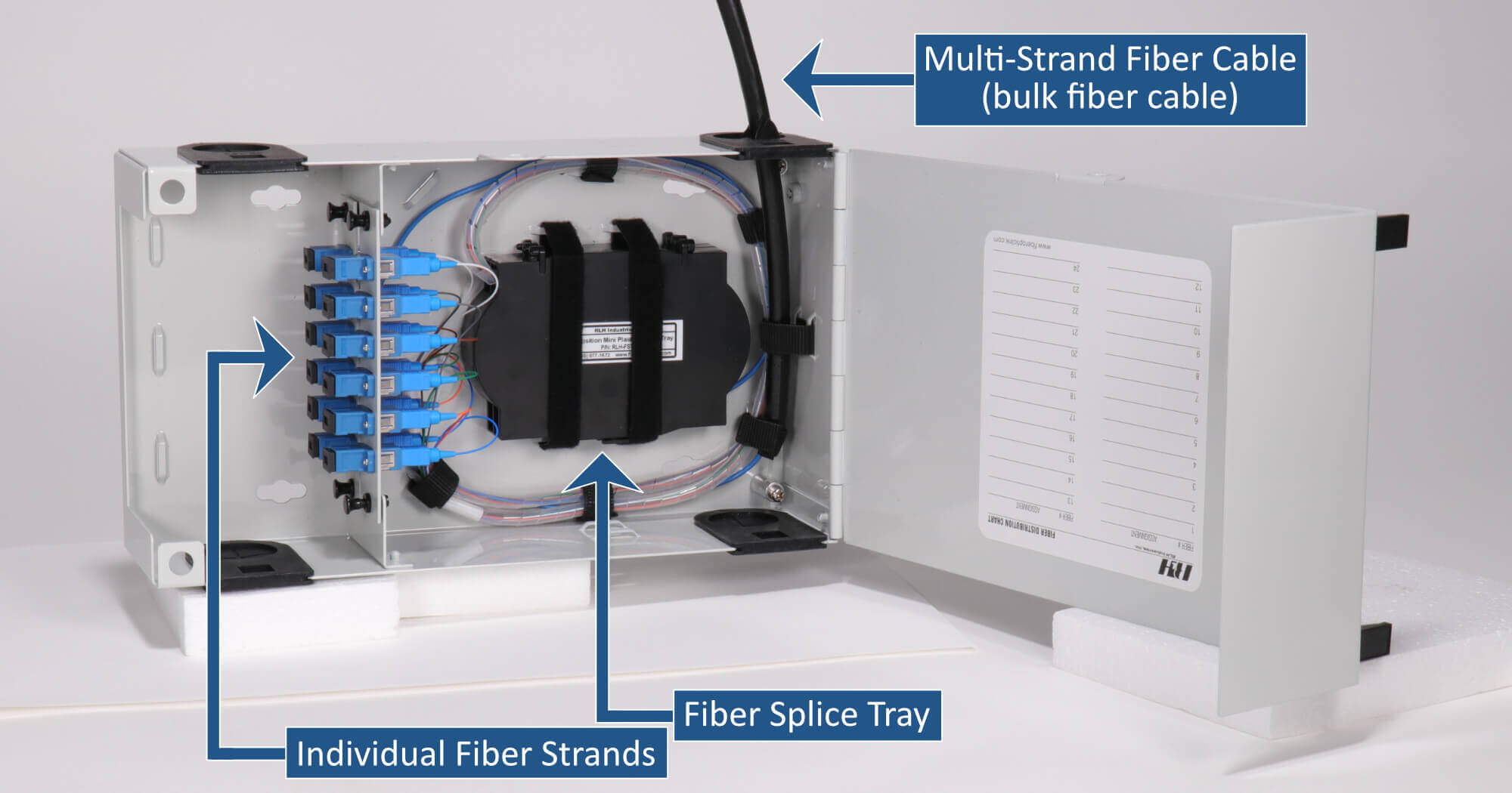
Fiber optic patch panels are enclosures that act as a distribution hub for fiber cable. A bulk (multi-strand) fiber cable enters the patch panel and then each fiber strand is separated into individual strands or pairs of strands. These individual strands will then connect to electronic devices designed to communicate over fiber optic cable.
The Location of Installation
The location of where the fiber optic patch panel is installed will help determine which type is needed. Fiber patch panel types are categorized by their installation location. The most common types of fiber patch panels are: Rack Mount, Wall mount, Outdoor, & DIN mount.
It is important to know the location of the installation as it will directly lead you to the type of patch panel needed. Making this determination is the first step for a successful installation.
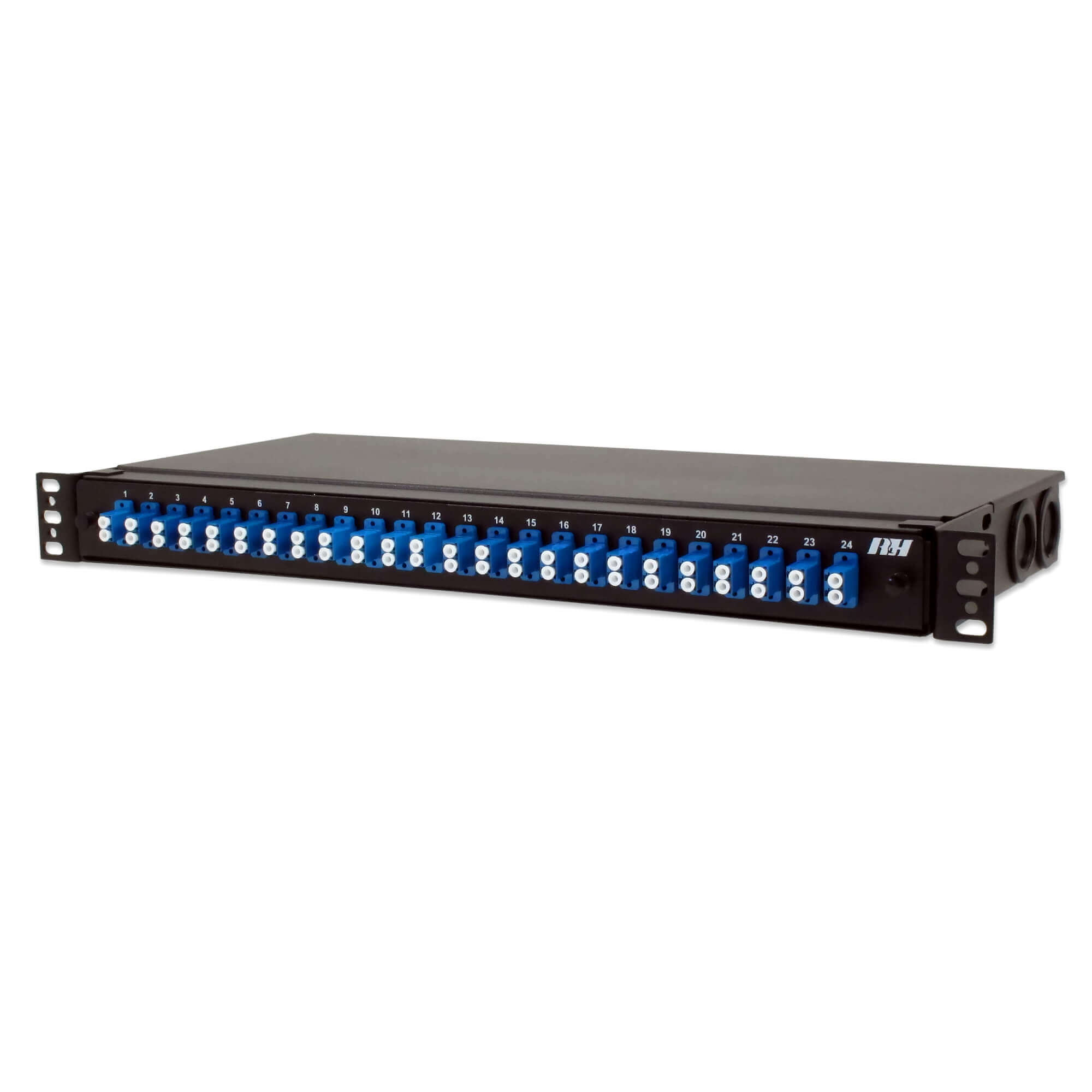
- Rack mounting of fiber patch panels is done with either 19” or 23” equipment racks, both defined by the EIA-310 Standard.
- The 19″ and 23″ refers to the horizontal spacing between the two vertical posts to which the equipment will mount.
- The 19″ rack is the more common between the two types.
- The vertical spacing between the mounting points is described as a Rack Unit, or RU. Each Rack Unit is 1-3/4 inches (44.5 mm).
- Rack mount fiber patch panels will typically specify how many rack units it will occupy when installed. The more rack units it occupies the more fiber the patch panel will typically accommodate.
- Wall mounting fiber optic patch panels is also very common.
- There’s a lot of variability between the options available for wall mount patch panels.
- The most common wall mount surfaces are a telco back board (3/4″ plywood), concrete, or a metallic panel.
- Outdoor fiber patch panels are specifically designed to be installed directly outdoors. They protect against rain, snow, dust, and wind.
- They are typically made from fiberglass, steel, or aluminum.
- Outdoor fiber patch panels should carry a NEMA rating (a NEMA 4 and higher rating is recommended). The NEMA rating defines the types of environmental protection the patch panel enclosure will provide.
- This type of fiber patch panel will typically accommodate wall or pole installations.
- DIN fiber optic patch panels are common in industrial installations where a DIN rail is the preferred type of mounting solution.
- The most common type of DIN rail in the United States is the T-35 DIN rail (IEC/EN 60715 Standard).
- DIN-mountable patch panels will include a DIN Clip, This clip attaches to the DIN rail and allows for quick installation and removal.
- DIN-mountable patch panels are designed to be small and lightweight to make them suitable for this type of installation.
Bulk Fiber Cable: Strand Count & Mode
Determining both the mode type and strand count of the bulk fiber cable that will enter the fiber optic patch panel is the next essential step. For the purposes herein, it will be assumed a cable is existing or has been already specified. Our focus will be on identifying the existing cable to ensure the patch panel is outfitted correctly.
Strand Count:
- Within a bulk fiber cable there will be multiple individual fiber strands. Higher strand count cables will typically bundle fiber strands in groups of 12 within the bulk cable.
- Typical strand counts are even numbers. If a cable exceeds 12 strands it will be in multiples of 12.
- Most commonly available strand counts are: 2, 4, 6, 12, 24, 48, 96, 144.
Mode Type:
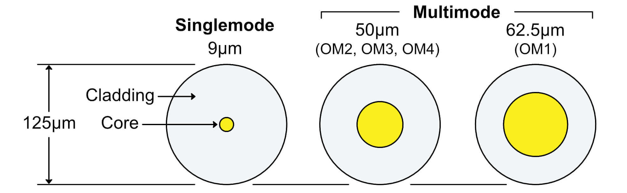
There are two common types of fiber cable, Singlemode & Multimode. Each type has a specific purpose and we will provide a quick overview of the differences.
- Singlemode fiber has a smaller core and is used for long-distance communication. This is typically fiber runs that are over 2km (1.2miles).
- Multimode 62.5µm (OM1) fiber has a larger core and used primarily for on-campus applications where fiber runs will be less than 2km.
- Multimode 50µm (OM2, OM3, or OM4) fiber has a slightly smaller core than the traditional multimode fiber. It is a newer fiber mode and was developed for high-speed applications. These mode types allow for higher data speeds over longer distances. While the core size is the same between OM2, OM3, or OM4, the grade of glass used in the fiber increases the higher the OM number.
Identifying the Strand and Mode:
Most fiber suppliers will print both the mode and fiber count on the jacket. Being familiar with the various mode types and common strand counts will help when trying to identify the relevant information. There is no standard for how the cables are identified, each cable manufacturer labels the jacket differently. Some manufacturers will only provide a part number, which you would then have to research to find the strand count and mode type.
Example:
- The highlighted words “12F” indicate the strand count, 12 fibers.
- The highlighted words “SM” indicates the mode type, singlemode.

Once the mode type and strand count have been identified it is important to keep that information available as it will guide the selection process for the fiber adapters.
Splice Trays
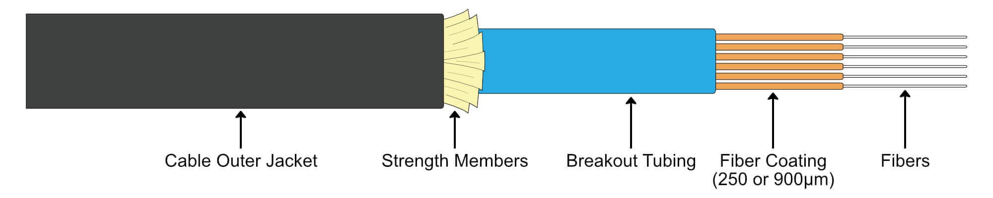
Determining whether a splice tray is needed is the next essential part of the patch panel selection process. When a bulk fiber cable enters a patch panel it must be separated into the individual strands inside the fiber patch panel and then terminated. A terminated fiber cable is a cable that has a connector installed on each fiber strand. The process of installing the connector is typically referred to as a fiber cable “break-out”.
A fiber technician will perform this process with specialized equipment. To break-out a fiber cable the jacket on the bulk fiber cable must be cut open and stripped back and the internal fiber bundles separated into individual fiber strands.
There are two methods a technician will use to break-out and then terminate a bulk fiber cable:
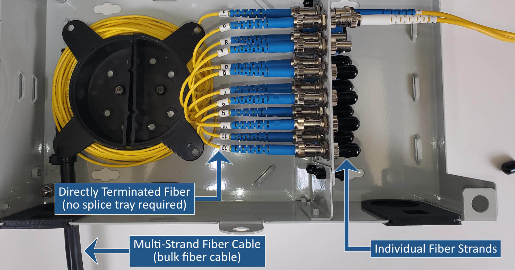
Direct Termination – Splice Tray not Required
No Splice Tray is required if the cables will be directly terminated with fiber connectors.
- This termination type involves installing a fiber connector directly onto the bulk fiber cable.
- The cable jacket is cut back, the strands are separated, and a connector is installed directly on the end of each fiber strand.
- This type of termination is the most time consuming, as epoxying and polishing the connectors is a slow and methodical process.
- A directly-terminated fiber cable is most common when a bulk fiber cable is ordered pre-terminated, with connectors already installed.
- Direct field termination is not common and typically only performed when there is a small number of fibers to terminate or specialty applications where limited spacing is available making splicing not be possible.
Fusion Splicing – Splice Tray Required
Splice Trays or Chips are required if fusion splicing fiber cable.
- This involves using heat to join two fibers together.
- The bulk fiber cable will be joined to a short length of matching fiber where the connectors have been pre-installed polished, and tested at the factory (fiber pigtail).
- Splicing is a quick process for a trained technician and the most common method for field termination.
- The spliced fiber connections are secured in the patch panel with splice trays or splice chips, which protect and organize the fiber splices.
If the cable will be directly terminated it will not require splice trays. If it is to be fusion spliced to fiber pigtails, it will require the use of splice trays. In order to select a suitable patch panel, it is essential to determine what type of fiber break-out will be performed. It is important to know that if fusion splicing is going to take place, a fiber splice tray will be required and to ensure the fiber patch panel selected will support the use of one.
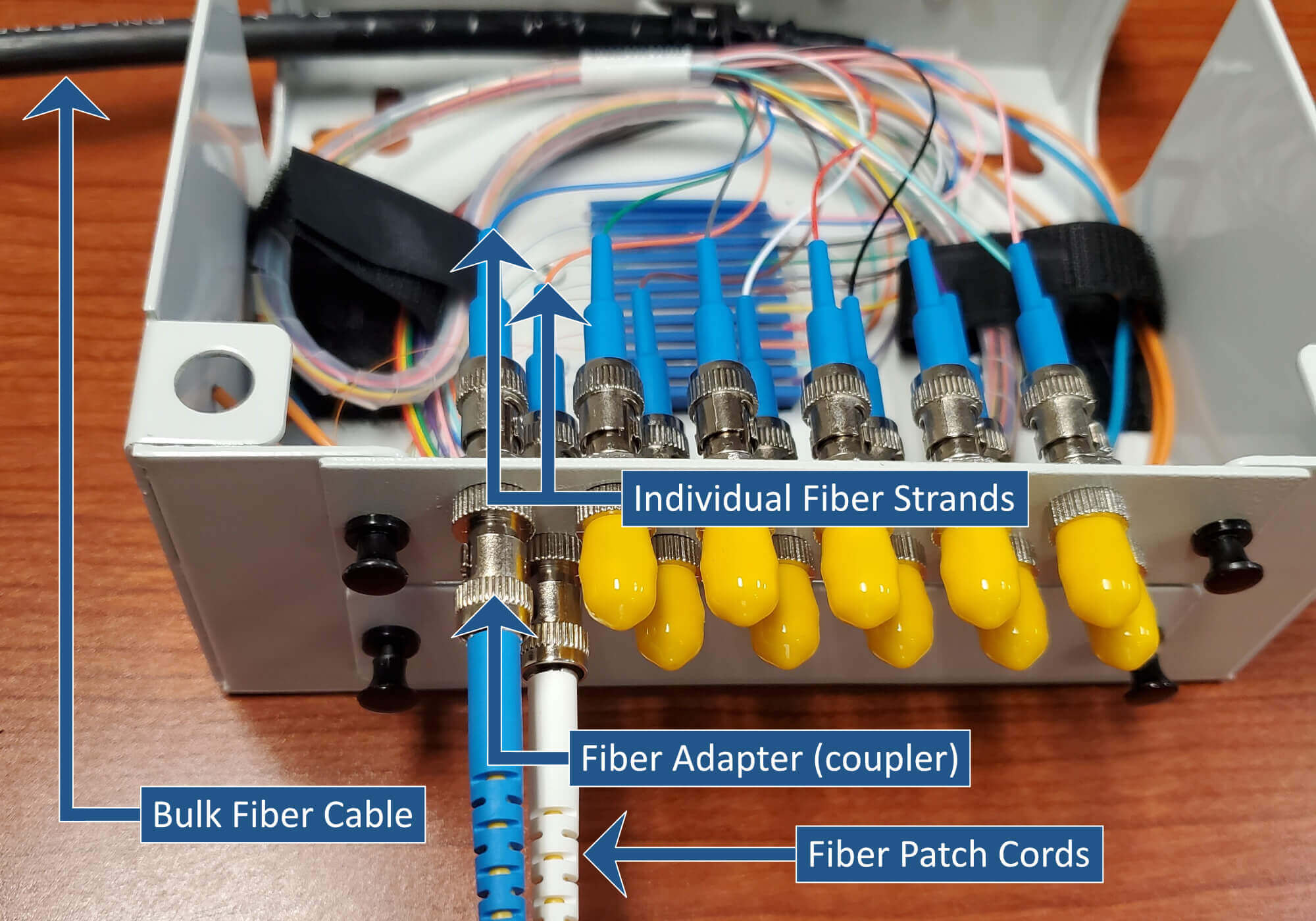
The Point of Connection
The point of connection is the interconnection point where the patch panel will provide the interface between a terminated bulk fiber cable and a fiber patch cord. The fiber adapter (coupler) will align your terminated bulk fiber cable with the fiber patch cord to insure there is a proper mating between the two cables.
Adapters
The fiber adapter is a critical part of the selection process and there are many different types commonly used. This is where the information gathered in regarding the fiber mode type will be required. The mode will be important as fiber adapters are color coded for the various modes available.
Once the mode of the bulk fiber cable is known, the type of connector to be used with the fiber adapter must be chosen. Designers use various types of connectors for different applications. You will need to select an adapter type based on the connector types to be used in the field. Each connector style below can be used with any type of fiber cable. Below is a list of common connector styles along with the uses most commonly seen in the field.
ST Connectors
- Slang: Stab & Twist
- Are an older style connector
- Most common use is with Multi-mode (OM1) fiber cable
SC Connectors
- Slang: Square Connector
- Are an older style connector
- Most common use is with singlemode fiber cable
LC Connectors
- Slang: Little Connector
- Popular where there is a high strand count since they are a smaller form factor
- These are the most popular style connector on the market today
- Widely used for all types of fiber
FC Connectors
- The least common out of the options shown and has therefore not yet earned a nickname
- When seen, used most with single mode fiber
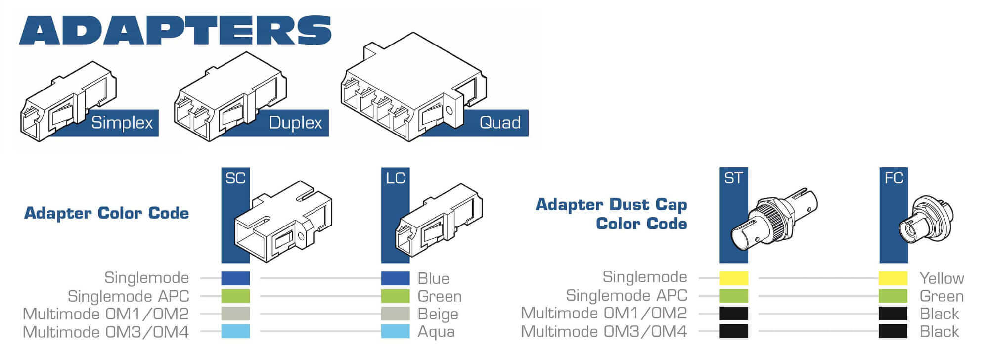
Once the Mode of fiber is known and the style of connector has been selected the following chart will identify the appropriate color code. For SC and LC adapters and the adapter itself will be color coded to represent the type of fiber being used. For ST and FC adapters the dust cap is used to represent the mode of fiber.
This graphic illustrates each type discussed and illustrates the proper TIA-598-C color coding that should be followed for use with different fiber mode types.
Adapters Plates or Built-in?
There are two main ways fiber adapters are incorporated into a fiber patch panel.
Fiber Patch Panels with Built-in Adapters
This is where the adapter is built-in to the patch panel and not meant to be remove or changed.
Pros:
- Typically more economical
- Ordering involves less decisions
Cons:
- Adapters can usually not be changed
- Capacity is fixed; adapters cannot be removed or added
- Not common for splicing applications
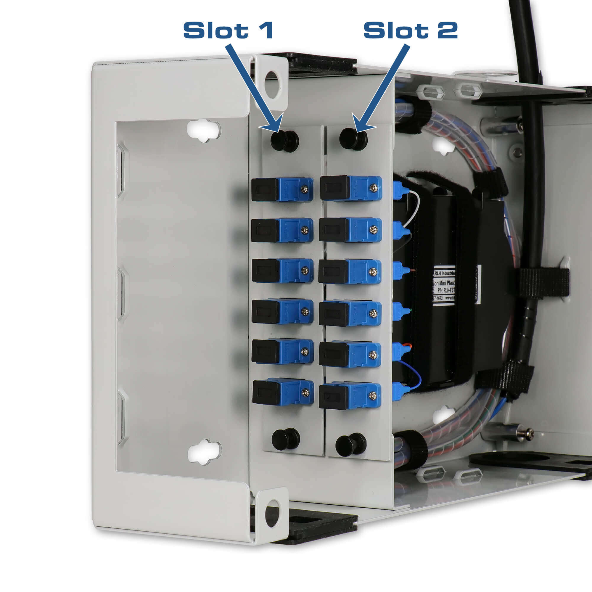
Fiber Patch Panels with Adapter Plate Slots
This is where the fiber patch panels will have slots or mounting points for adapter plates to be installed into. Adapter plates hold the fiber adapters and then are used to populate the slots in the fiber patch panel. The adapter plates are sold separately and are typically pre-configured with a configuration code.
Pros:
- Modular – buy what is needed with the opportunity to expand later
- Flexible – each slot can accommodate a different adapter style
- Easy to change the adapter type when necessary
- Most common type of fiber patch panel
Cons:
- Can make ordering more complex
- Adapter plates are not always universal between manufacturers
The Final Selection
Armed with the following information, selecting a suitable patch panel for your installation should be possible. There’s many different options available and there are alternatives and innovative solutions out there. But after reading this guide a novice should have a much better understanding of the wold surrounding fiber patch panels.
If you’re interested in learning more about fiber optics, you might want to check out Fiber Optic Converters: A Beginner’s Guide.
- Installation location
- Bulk fiber cable specs: strand count & mode
- Splice tray required?
- Adapter type desired
- Built-in adapters or adapter plates
Learn More
- About Fiber Optics – The Fiber Optic Association: https://www.thefoa.org/
- About EIA Standards – Electronic Industries Alliance: https://www.ecianow.org/
- About NEMA Standards – National Electrical Manufacturers Association: https://www.nema.org/standards
- About IEC Standards – International Electrical Commissions: https://iectest.iec.ch/
- About TIA Standards – Telecommunications Industry Association: https://tiaonline.org/